Dismantling modern structures engineered to resist high lateral forces and shear stress requires specialized equipment capable of overcoming dense reinforcement matrices. Utilizing underpowered or improperly specified attachments on heavily reinforced concrete or high-tensile steel leads to accelerated blade wear, hydraulic failure, extended project timelines, and compromised site safety. Selecting the correct attachment requires translating structural engineering parameters—such as ACI 318 compliance, shear wall density, and punching shear reinforcement—into specific equipment requirements. Operators face distinct challenges when transitioning from standard commercial teardowns to heavy industrial dismantling. The reinforcement density dictates the mechanical approach. You must match the jaw configuration, cylinder size, and hydraulic flow to the exact structural resistance of the building. This guide provides a technical framework for evaluating and specifying equipment based on the structural realities of the target asset.
Structural Alignment: The choice between a concrete demolition shear and a structural steel shear must be dictated by the primary load-bearing materials and reinforcement density (e.g., heavy rebar vs. steel I-beams).
Decoupling $V_c$ and $V_s$: Understanding the structural balance between concrete-derived shear strength ($V_c$) and steel reinforcement shear strength ($V_s$) dictates whether a contractor should prioritize jaw crushing force or blade cutting efficiency.
Hydraulic Compatibility: Attachment performance is strictly bound by the base excavator’s hydraulic flow (GPM) and operating pressure; mismatched systems cause critical cycle time delays.
Multi-Processor Versatility: For mixed-material structures, interchangeable jaw systems offer operational flexibility but require evaluating the trade-off between specialized power and general utility.
Analyzing Structural Shear Design for Demolition Planning
To effectively destroy a structure, contractors must understand how it was designed to stand. Evaluating the structural engineer's original shear design dictates the necessary crushing force and cutting capacity. Different zones within a single building present wildly different resistance profiles. You cannot approach a post-tensioned parking garage with the same equipment used for a structural steel warehouse. The mechanical properties of the target material dictate the required hydraulic pressure and jaw geometry.
Reinforced Concrete Beams and Slabs (The Vn = Vc + Vs Framework)
Evaluate nominal shear strength by identifying the ratio between concrete shear capacity and steel reinforcement shear capacity. Concrete provides excellent compressive strength but fails rapidly under tension. Engineers compensate for this by embedding steel rebar. Assess the density of shear reinforcement, typically Grade 60 stirrups designed to prevent diagonal tension failures. High steel reinforcement values require an attachment with superior throat-cutting force. Differentiate between simply supported and continuous beams. Identify high-shear zones near support columns where stirrup spacing is tightest, marking these as critical targets for the demolition equipment. When you encounter #4 or #5 stirrups spaced at three-inch intervals near a column drop panel, the attachment must crush the concrete shell and immediately shear the dense steel cage without jamming.
Contractors often underestimate the force required to break the bond between high-strength concrete and deformed rebar. The crushing teeth must penetrate the concrete cover, exposing the core reinforcement. Once exposed, the secondary blades located deep in the jaw throat take over. If the jaw lacks the necessary closing force, the rebar will fold rather than cut, leading to tangled debris that slows down secondary processing and loading operations.
Transfer Slabs and Two-Way Flat Slabs (Punching Shear Zones)
Identify structural zones vulnerable to punching shear failure, which govern the design of transfer slabs and two-way flat slabs. Map the critical shear perimeter where shear reinforcement is heavily concentrated. Select attachments capable of penetrating localized zones of extreme rebar density and thick concrete profiles without stalling. Transfer slabs often exceed 36 inches in thickness and contain multiple mats of heavy rebar, sometimes up to #11 bars. These slabs transfer the load of upper-story columns to a different grid pattern below, making them massive reservoirs of stored energy and structural resistance.
Dismantling these zones requires a systematic approach. You must attack the slab from the edges, working inward to relieve the structural tension gradually. The attachment must feature a wide jaw opening to accommodate the slab thickness and sufficient cylinder power to crack the concrete matrix. Operators should target the mid-span sections first, where the shear reinforcement is less dense, before moving to the heavily reinforced column capitals.
Shear Walls and Lateral Force Resisting Systems
Identify structural cores and shear walls built to withstand wind and seismic activity using specialized boundary elements and dense horizontal or vertical steel configurations. Note the concrete compressive strength and the tightly spaced, multi-layered rebar grids that require specialized equipment to separate steel from concrete effectively. Elevator cores and stairwell shafts often serve as the primary lateral force-resisting systems in high-rise buildings. These walls feature heavily confined boundary elements at their edges, packed with vertical rebar and tightly spaced horizontal ties.
Breaking down a shear wall requires an attachment that can bite through the boundary elements without deflecting. The jaw must grip the wall, crush the high-PSI concrete, and shear the dense rebar cage in a single fluid motion. If the attachment twists or deflects during the cut, it places immense strain on the excavator's boom and stick cylinders, potentially causing catastrophic equipment failure.
Structural Steel Frames and Connections
Analyze the thickness and yield strength of structural steel columns, beams, and gusset plates. Determine the requirement for attachments that can cleanly slice through heavy steel without stalling or twisting the jaw. Modern steel structures utilize high-strength alloys like A992 steel, which offers a yield strength of 50,000 PSI. The connections between these members—moment frames, bolted gusset plates, and heavy weldments—present the greatest challenge during demolition.
When attacking a steel connection, the operator must position the jaw to shear the bolts or the thinner web of the beam rather than attempting to cut through the thickest part of the flange directly. The attachment must feature a piercing tip to initiate the cut and tight blade tolerances to prevent the steel from folding and jamming between the upper and lower jaws.
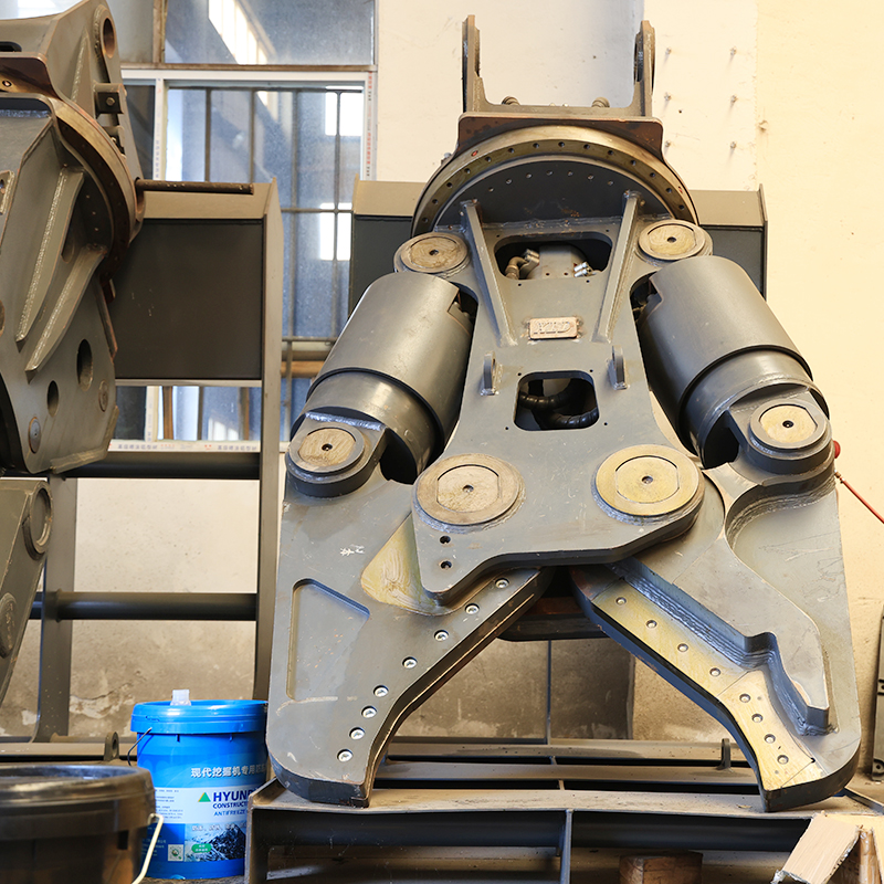
Categorizing Demolition Shear Solutions
Mapping the structural analysis to the primary categories of demolition attachments ensures optimal performance on the job site. Using the wrong tool for the material guarantees poor production rates and excessive wear on the base machine. You must match the attachment's design intent to the physical reality of the structure.
Concrete Demolition Shears (Processors/Pulverizers)
These units are designed primarily for crushing concrete and exposing structural rebar. They feature wide jaws with crushing teeth and secondary cutting blades located near the throat for snipping exposed reinforcement. A dedicated concrete demolition shear is best suited for standard reinforced concrete dismantling and high-reach processing. The primary function is volume reduction. The teeth shatter the concrete matrix, allowing the pulverized material to fall away while the rebar is retained in the jaw for cutting.
The geometry of the jaw is optimized for grabbing large, irregular chunks of concrete. The cylinders are sized to provide maximum crushing force at the tips of the jaws, where the initial contact occurs. Once the concrete is broken, the operator shifts the material deeper into the throat, where the cutting blades sever the remaining steel reinforcement. This two-stage process is essential for efficient primary demolition and secondary material sorting.
Dedicated Structural Steel Shears
Engineered with a piercing tip and heavy-duty cutting blades designed to shear metal, these attachments feature tighter jaw tolerances to prevent thin steel from folding between the blades. A structural steel shear is mandatory for dismantling steel-framed buildings, heavy industrial sites, and processing scrap. Unlike concrete processors, these attachments are not designed to crush material. Their sole purpose is to slice through steel members with surgical precision.
The jaw design features an offset profile that draws the material into the throat as the jaw closes. This prevents the steel from slipping out of the bite and maximizes the mechanical advantage of the hydraulic cylinder. The piercing tip is critical for initiating cuts in flat plates or large box sections, creating a weak point that the main blades can exploit.
Multi-Processors (Interchangeable Jaws)
These are base housing units that accept multiple jaw sets, including concrete crackers, steel shears, and pulverizers. They are ideal for hybrid structures but require evaluating the time cost of swapping jaws versus utilizing dedicated machines. A multi-processor offers unmatched versatility on complex sites where the structural materials change from floor to floor or section to section.
However, this versatility comes with a trade-off. Multi-processors are generally heavier than dedicated attachments of the same size class, which reduces the safe working reach of the excavator. Additionally, the process of swapping jaws, even with quick-change systems, introduces downtime. Site managers must calculate whether the flexibility outweighs the loss of continuous production.
Technical Evaluation Dimensions for Shear Selection
Quantitative metrics are required to vet equipment specifications against project demands accurately. Relying on visual inspections or manufacturer marketing claims often leads to undersized equipment and stalled projects. You must run the numbers on hydraulic flow, operating pressure, and mechanical force curves.
Matching Structural Capacity to Jaw Force Curves
Translate structural shear capacity equations into required attachment force. Ensure the jaw force exceeds the calculated structural resistance at the point of engagement. Evaluate the force-to-weight ratio. Maximum cutting force is typically generated at the throat of the jaw; evaluate manufacturer claims based on throat force, not just tip force. Assess jaw depth and opening width against the maximum cross-section of the structural members being demolished.
Calculate the maximum cross-sectional area of the steel members on the site.
Determine the yield strength of the steel (e.g., 36,000 PSI for older A36 steel, 50,000 PSI for modern A992 steel).
Multiply the cross-sectional area by the yield strength to determine the absolute minimum cutting force required.
Select an attachment that delivers a throat cutting force at least 20% higher than the calculated minimum to account for blade wear and hydraulic inefficiencies.
The force curve of a hydraulic attachment is not linear. The cutting force increases dramatically as the material is pushed deeper into the throat, closer to the main pivot pin. Operators must be trained to position the material correctly to leverage this mechanical advantage. Attempting to cut heavy steel at the tips of the jaw will stall the attachment and cause excessive wear on the pivot group.
Hydraulic Requirements and Cycle Times
Verify the operating pressure and flow rate required by the attachment against the base machine’s capabilities. Evaluate the presence of speed valves that rapidly close the jaw under low load, significantly reducing cycle times and improving daily tonnage output. The hydraulic system is the lifeblood of the attachment. If the excavator cannot deliver the required gallons per minute (GPM) at the specified pressure, the attachment will perform poorly, regardless of its mechanical design.
| Excavator Weight Class | Typical Hydraulic Flow (GPM) | Typical Operating Pressure (PSI) | Recommended Attachment Type |
| 20 - 25 Tons | 40 - 55 | 4,500 - 5,000 | Light-duty multi-processors, secondary pulverizers |
| 30 - 40 Tons | 60 - 80 | 5,000 - 5,500 | Standard concrete processors, medium steel shears |
| 45 - 60 Tons | 85 - 110 | 5,000 - 5,500 | Heavy-duty structural steel shears, primary crushers |
| 70+ Tons | 120+ | 5,500+ | Massive primary demolition shears, high-reach applications |
Speed valves, also known as regeneration valves, route hydraulic fluid from the rod end of the cylinder directly to the head end during the closing stroke. This allows the jaw to close rapidly until it encounters resistance, at which point the valve shifts, and full system pressure is applied to complete the cut. This technology can reduce cycle times by up to 30%, drastically increasing the amount of material processed per shift.
Base Machine Compatibility and Reach
Calculate the safe working load of the excavator, factoring in the weight of the attachment at maximum reach. Account for the center of gravity and its impact on machine stability during high-angle cuts on vertical shear walls. A heavy attachment mounted on a standard boom may cause the excavator to tip forward when working over the side of the tracks. You must consult the excavator's lift chart and ensure the combined weight of the attachment and the quick coupler falls within the safe operating zone.
When utilizing high-reach demolition booms, the weight restrictions become even more severe. The attachment must be specifically sized for the high-reach configuration, which often means sacrificing jaw size and cutting force for reduced weight. Operators must adapt their techniques, taking smaller bites and relying on the attachment's precision rather than brute force to dismantle the structure safely.
Matching Shear Capabilities to Structural Outcomes
Specific features solve distinct structural dismantling challenges encountered on complex sites. You must align the mechanical design of the attachment with the physical properties of the target material. A mismatch here leads to inefficient processing and increased wear on the equipment.
Overcoming Punching Shear Reinforcement
Utilize attachments with specialized tooth configurations designed to penetrate and fracture dense concrete nodes around column heads before cutting the rebar. The teeth must be sharp enough to create localized stress fractures in the concrete, allowing the jaw to crush the material without requiring excessive hydraulic pressure. Once the concrete is fractured, the secondary blades can easily sever the exposed shear studs and heavy rebar mats.
Operators should approach punching shear zones at an angle, targeting the corners of the column drop panels where the reinforcement is slightly less dense. By nibbling away at the edges, the operator can gradually reduce the structural integrity of the node before attempting a full-depth bite. This methodical approach prevents the attachment from stalling and reduces the risk of sudden structural collapse.
Processing Heavy Rebar and Concrete Separation
Evaluate the efficiency of the throat blades in cutting heavy structural rebar cleanly, preventing long, tangled strands that disrupt debris loading. When processing heavily reinforced concrete, the goal is to separate the steel from the concrete as cleanly as possible. The attachment must crush the concrete into manageable pieces while simultaneously cutting the rebar into short lengths that can be easily handled by a magnet or grapple.
If the throat blades are dull or improperly gapped, the rebar will fold and slip between the blades, creating long, tangled "bird nests" of steel. These tangles are incredibly difficult to load into trucks and pose a significant safety hazard on the site. Regular maintenance and blade indexing are critical to ensuring clean cuts and efficient material separation.
Slicing High-Tensile Structural Steel
Prioritize attachments with an offset jaw design or piercing tip that initiates the cut effectively, reducing the risk of material deflection or blade jamming. High-tensile steel requires a different approach than mild steel or rebar. The attachment must pierce the material to create a stress concentration point, then shear the steel using a scissor-like action. The offset jaw design ensures the material is drawn into the throat, maximizing the cutting force and preventing the steel from slipping out of the bite.
When cutting large I-beams or box columns, the operator should first pierce the web of the beam before attempting to cut the thicker flanges. This two-step process reduces the strain on the attachment and ensures a clean, predictable cut. Attempting to cut through the entire cross-section of a heavy beam in a single bite often leads to stalled cylinders and damaged blades.
Implementation Risks and Operational Economics
Identifying hidden costs and operational hazards associated with demolition attachments is critical for project success. Equipment failures and unplanned downtime can quickly erode project margins. You must proactively manage the wear parts and hydraulic systems to maintain peak performance.
Blade Wear and Maintenance Downtime
Abrasive concrete and high-tensile steel rapidly degrade cutting edges, leading to folded material and jammed jaws. Select units with reversible, indexable blades that can be rotated on-site with standard hand tools, minimizing maintenance downtime. The cutting blades are the most critical wear parts on the attachment. As they wear, the gap between the upper and lower blades increases, reducing cutting efficiency and causing material to fold.
Indexable blades feature multiple cutting edges. When one edge becomes dull, the operator can unbolt the blade, rotate it to expose a fresh edge, and bolt it back into place. This process takes minutes and restores the attachment to peak cutting performance. Neglecting blade maintenance leads to increased hydraulic strain, higher fuel consumption, and accelerated wear on the pivot group.
Hydraulic System Strain
Operating an attachment on an under-specced excavator leads to hydraulic overheating, sluggish performance, and premature pump failure. Conduct a strict hydraulic audit prior to procurement; consider dedicated auxiliary hydraulic cooling systems for continuous demolition environments. The continuous opening and closing of the jaw generate significant heat within the hydraulic system. If the excavator's cooling system cannot dissipate this heat, the hydraulic fluid will thin out, reducing system pressure and cutting force.
In severe cases, overheated hydraulic fluid can damage the seals within the attachment's cylinders and the excavator's main pumps. Installing a dedicated auxiliary cooling circuit ensures the hydraulic fluid remains within the optimal temperature range, even during continuous, heavy-duty processing. This investment protects the base machine and ensures consistent attachment performance throughout the shift.
Operator Safety and Debris Management
Improper cutting angles or inadequate force can cause structural members to snap unpredictably or generate hazardous flying debris. Ensure the unit features 360-degree continuous hydraulic rotation for optimal positioning, allowing the operator to make perpendicular cuts safely. The ability to rotate the attachment under load is essential for safe and efficient dismantling. It allows the operator to align the jaws perfectly with the structural member, ensuring a clean cut and preventing the material from twisting or deflecting.
Continuous rotation also improves debris management. The operator can grab a severed beam, rotate it into the optimal position, and carefully lower it to the ground or place it directly into a processing pile. This level of control reduces the risk of dropping material and minimizes the need for secondary handling by ground crews.
Conclusion
The successful dismantling of reinforced structures relies on precisely matching your equipment to the engineer's original structural design. You must evaluate the reinforcement density, the concrete compressive strength, and the steel yield strength before selecting an attachment. Take the following steps to ensure project success:
Audit the primary structural materials and nominal shear capacities of the target building.
Verify the hydraulic flow and operating pressure of your base machine against the attachment requirements.
Select jaw configurations based on the densest reinforcement zones, prioritizing throat force for heavy steel.
Implement a strict maintenance schedule for indexing and rotating cutting blades to maintain efficiency.
FAQ
Q: How do I choose between a concrete processor and a dedicated steel shear?
A: Base your choice on the primary load-bearing material. If the structure is heavily concrete with embedded rebar, use a concrete processor. If it is primarily structural steel I-beams and columns, a dedicated steel shear is required.
Q: Why is throat force more important than tip force?
A: The throat of the jaw is closest to the pivot point, generating the maximum mechanical advantage and highest cutting force necessary for severing thick steel members or dense rebar bundles.
Q: Can I use a shear on an excavator with lower hydraulic flow than recommended?
A: No. Operating with insufficient hydraulic flow results in sluggish cycle times, reduced cutting force, and potential overheating of the excavator's hydraulic system.
Q: What is the benefit of a 360-degree continuous rotation feature?
A: Continuous rotation allows the operator to position the jaw perfectly perpendicular to the structural member, ensuring a clean cut, reducing blade wear, and improving overall site safety.
Q: How often should cutting blades be rotated or replaced?
A: Blade maintenance depends on the material being processed. Inspect blades daily. Rotate or index them as soon as edges become rounded or if you notice material folding instead of cutting cleanly.

 English
 العربية
 Français
 Русский
 Español
 Português
 Deutsch
 italiano
 日本語
日本語 한국어
한국어 Nederlands
 Tiếng Việt
 ไทย
ไทย Polski
 Türkçe
 አማርኛ
አማርኛ ພາສາລາວ
 ភាសាខ្មែរ
 Bahasa Melayu
 ဗမာစာ
ဗမာစာ தமிழ்
தமிழ் Filipino
 Bahasa Indonesia
 magyar
 Română
 Čeština
 Монгол
 қазақ
қазақ Српски
 हिन्दी
 فارسی
فارسی Kiswahili
 Slovenčina
 Slovenščina
 Norsk
Norsk Svenska
 українська
 Ελληνικά
 Suomi
Suomi Հայերեն
 עברית
עברית Latine
 Dansk
Dansk اردو
اردو Shqip
Shqip বাংলা
বাংলা Hrvatski
 Afrikaans
 Gaeilge
 Eesti keel
 Māori
Māori


