Incorrectly sizing equipment for steel cutting introduces severe operational and financial risks. Undersizing leads to premature equipment failure, catastrophic structural fatigue, and stalled production schedules. You risk snapping blades and burning out hydraulic pumps when pushing a machine past its limits. Conversely, oversizing results in wasted capital expenditure, inefficient cycle times, and excessive energy consumption. Matching machine specifications to specific cutting realities is a strict engineering task. You must account for varying tensile strengths, plate thicknesses, profile geometries, and the physical constraints of your operational environment.
Determining the exact specifications required demands a systematic evaluation framework. Whether you are outfitting a precision fabrication shop, managing a high-volume scrapyard, or equipping a heavy-duty demolition site, selecting the right equipment ensures continuous operation and maximizes material throughput. This guide provides the technical criteria needed to evaluate capacity, geometry, and carrier compatibility to ensure your equipment matches your production demands perfectly.
Material Dictates Capacity: Maximum material thickness, profile shape, and tensile strength (e.g., mild vs. carbon steel) are the baseline metrics for determining required tonnage.
The Hydraulic Threshold: Manual and electric shears are limited to thin sheet metals; heavy-duty plates and structural steels mandate a dedicated hydraulic shear.
Clearance and Geometry Matter: Jaw opening and throat depth are just as critical as raw cutting force; a machine cannot cut what it cannot physically accept or hold securely.
Environment Defines Configuration: Stationary shop shears prioritize precision and backgauge automation, while an excavator hydraulic shear prioritizes carrier compatibility, weight distribution, and mobility.
Operational Value Extends Beyond Purchase Price: Blade reversibility, hydraulic efficiency, and maintenance intervals heavily influence the long-term viability of the chosen size.
Defining Your Steel Cutting Success Criteria
Material Specifications, Thickness, and Yield Strength
Evaluating the maximum thickness and length of the material to be cut establishes your baseline equipment requirements. Thin sheet metals and light-gauge aluminum can often be processed using manual or electric shears. However, when operations scale to heavy-duty plates, structural profiles, and high-tensile alloys, a hydraulic system becomes mandatory. You need fluid power to provide the necessary shearing force without stalling or fracturing the blade.
Material hardness and tensile strength directly alter the required cutting force. Mild steel requires significantly less tonnage to shear compared to high-carbon steel or specialized alloys. When calculating capacity, you must size the machine based on the hardest, thickest material you intend to process regularly. Cutting mixed, non-uniform scrap presents a different challenge than processing uniform steel plates. Scrap processing requires a machine capable of handling unpredictable cross-sections and varying yield strengths in a single cycle. You must build higher safety factors into your tonnage calculations for scrap applications.
| Material Type | Typical Yield Strength (MPa) | Shear Force Multiplier | Recommended Application Focus |
| Mild Steel (A36) | 250 - 290 | 1.0x (Baseline) | Standard fabrication, general scrap |
| High-Carbon Steel | 400 - 550 | 1.5x - 1.8x | Heavy equipment manufacturing, rail scrap |
| Stainless Steel (304) | 215 - 250 | 1.4x (Due to work hardening) | Food grade fabrication, chemical plants |
| Hardox / AR400 | 1000+ | 3.0x+ | Mining equipment repair, specialized demolition |
Production Volume, Cycle Times, and Throughput
Throughput requirements dictate the mechanical and fluid power specifications of your equipment. Low-volume precision fabrication focuses on accuracy and clean edges. This allows for slower cycle times. In contrast, high-cycle continuous scrap processing demands rapid jaw movement to maximize tons processed per hour. You measure success in a scrapyard by the volume of material downsized per shift.
Cycle time requirements directly influence hydraulic pump sizing, motor horsepower, and cooling system needs. Faster cycle times require higher hydraulic flow rates. If the pump and motor are undersized for the desired speed, the system will overheat. This leads to fluid degradation and component failure. High-throughput environments require robust cooling circuits to maintain optimal hydraulic fluid viscosity during continuous operation. You must match the cooling capacity to the ambient temperature of your working environment.
Core Dimensions for Sizing a Hydraulic Shear
Cutting Capacity and Tonnage Requirements
Industry-standard benchmarks provide a starting point for capacity evaluation. Standard industrial stationary shears typically handle mild steel up to 25mm thick. Heavy-duty models scale up to process plates exceeding 45mm. However, thickness alone does not determine capacity. You must calculate the mathematical relationship between material cross-section, tensile strength, and required shear tonnage to prevent machine overloading.
Required tonnage is a function of the material's ultimate tensile strength multiplied by the cross-sectional area being sheared. Attempting to cut material that exceeds the machine's rated tonnage causes hydraulic bypass. The fluid dumps over the relief valve, halting the cut instantly. Repeatedly pushing a machine to its maximum tonnage limit accelerates structural fatigue in the housing and pivot points. Always size the machine with a 20% tonnage buffer above your maximum calculated requirement.
Jaw Opening, Throat Depth, and Material Geometry
Jaw opening is the primary limiting factor for scrapyards and structural steel processing. A machine cannot process material that cannot physically fit between the blades. Specific structural profiles, such as H-beams, thick-walled pipes, and dense rebar bundles, dictate jaw geometry beyond standard flat plate calculations. The jaw must be wide enough to accept the profile and deep enough to position the material close to the pivot point. The pivot point is where cutting force is maximized.
For stationary fabrication applications, throat depth impacts the ability to slit long plates. A deeper throat allows operators to pass wider sheets through the frame for continuous slitting operations. If the throat is too shallow, the material will strike the machine frame. This limits the maximum width of the cut and forces operators to manually reposition heavy plates, destroying productivity.
Blade Length, Bed Capacity, and Rake Angle
Blade length and bed capacity limit the maximum sheet or plate width that can be processed in a single cycle. Attempting to cut material wider than the blade requires multiple strokes. This introduces step marks and reduces edge quality. The rake angle—the angle of the upper blade relative to the lower blade—also plays a critical role in capacity and cut quality.
Adjustable rake angles offer operational flexibility. Steeper angles allow the machine to cut thicker materials using less tonnage by reducing the contact area between the blade and the steel. However, steep rake angles can cause material distortion, such as bowing, twisting, or cambering, especially when cutting thinner sheets. Flatter rake angles minimize distortion but require higher tonnage to execute the cut. You must balance tonnage capacity against the acceptable level of material distortion for your specific application.
Stationary vs. Mobile Hydraulic Shear Configurations
Industrial Shop Shears for Fabrication
Stationary guillotine and swing-beam shears are engineered for precision plate processing in controlled shop environments. Guillotine designs drive the upper blade straight down. This offers high capacity and minimal distortion for thick plates. Swing-beam designs utilize a pivoting upper beam. This reduces maintenance points but slightly alters the blade clearance throughout the stroke.
Integrating precision features is essential for fabrication efficiency. A 36-inch power backgauge with LED readouts streamlines measuring, ensures repeatable cutting lengths, and minimizes operator error. Automated backgauges allow operators to program multiple cut dimensions. This significantly reduces setup time between different production runs and eliminates manual measuring mistakes.
Sizing an Excavator Hydraulic Shear
When sizing an excavator hydraulic shear, the critical dependency is carrier weight. The attachment weight must match the excavator's lifting capacity and stability parameters. Mounting a heavy attachment on a small carrier creates severe tipping hazards. This is especially dangerous when operating at full reach over the side of the tracks. You must also account for mounting location. Stick-mounted configurations offer better reach. Boom-mounted configurations provide higher lifting capacity for heavier attachments.
Matching the attachment’s operating pressure and hydraulic flow requirements (GPM/LPM) to the carrier’s auxiliary hydraulic circuit is mandatory. Insufficient flow results in sluggish jaw movement and poor productivity. Excessive pressure or flow can blow seals and damage the attachment's internal components. Proper hydraulic integration ensures the machine operates efficiently without overheating the carrier's fluid.
| Carrier Weight Class (Tons) | Typical Shear Weight (kg) | Required Flow (LPM) | Optimal Application |
| 10 - 15 | 800 - 1,200 | 100 - 150 | Light scrap, secondary downsizing |
| 20 - 25 | 1,800 - 2,500 | 180 - 250 | Standard demolition, structural steel |
| 30 - 40 | 3,000 - 4,500 | 250 - 350 | Heavy industrial demolition, thick I-beams |
| 50+ | 5,000+ | 350+ | Primary heavy scrap processing, shipbreaking |
Mobile Hydraulic Shear and Demolition Applications
Dynamic, on-site environments require equipment designed for mobility and ruggedness. A mobile hydraulic shear provides the agility needed to dismantle structures and process scrap directly at the source. Sizing a demolition hydraulic shear depends entirely on the specific phase of the project.
Primary demolition involves structural dismantling. This requires high reach and the ability to cut structural I-beams and columns in place. Secondary demolition focuses on material downsizing on the ground. This prioritizes faster cycle times to prepare scrap for transport. The attachment must be sized to handle the thickest structural steel present on the site while remaining agile enough to navigate debris piles safely.
Single vs. Double Cylinder Hydraulic Shear Designs
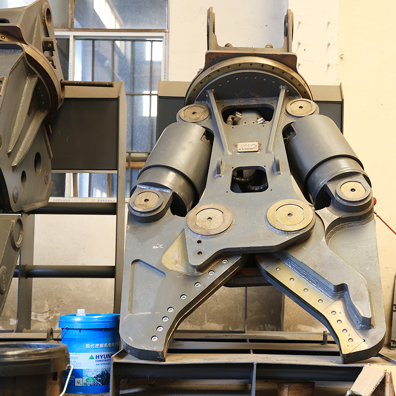
The mechanical design of the jaw actuation system impacts cutting performance and durability. A double cylinder hydraulic shear provides balanced force distribution across the jaw. This dual-actuation delivers higher crushing force for complex shapes. It significantly reduces torsional stress on the main housing, preventing the jaws from twisting when cutting uneven structural scrap.
Single-cylinder models offer different advantages. They typically feature faster cycle times due to lower fluid volume requirements. The simplified design reduces overall attachment weight. This allows it to be mounted on smaller carriers. It also requires less maintenance due to fewer hydraulic seals and pivot points. The choice depends on whether the application demands maximum piercing force or rapid processing speed.
Evaluating Operational Value
Power Consumption and Hydraulic System Efficiency
System efficiency directly impacts daily operational overhead. Oversized electric motors draw higher energy loads. This leads to wasted utility costs during idle times or when processing light materials. However, undersized motors are equally problematic. An undersized motor will frequently stall under heavy loads. This causes the hydraulic system to bypass fluid over the relief valve. This generates excessive heat, leading to rapid hydraulic fluid degradation and potential pump failure.
Optimizing hydraulic efficiency requires matching the pump displacement and motor horsepower to the specific cycle time and tonnage requirements. Variable displacement pumps offer a distinct advantage. They automatically adjust flow based on system pressure. This provides high speed during the approach stroke and high force during the cutting stroke, optimizing power consumption perfectly.
Blade Wear, Reversibility, and Maintenance Downtime
Sizing directly impacts consumable lifespan. Pushing a machine to its maximum capacity continuously accelerates blade wear. It dulls cutting edges rapidly and risks structural damage to the blade seat. Properly sized equipment operates within its optimal load range. This extends the life of consumables and reduces maintenance frequency.
To minimize maintenance downtime, evaluate the blade configuration carefully. Multi-edge reversible blades allow operators to rotate the cutting edge multiple times before requiring replacement or regrinding. Quick-change blade systems and accessible shim adjustments are critical for maintaining optimal blade clearance. Incorrect blade clearance causes material to fold between the jaws rather than shear. This jams the machine and damages the cutting edges instantly.
Implementation Risks, Setup, and Safety Compliance
First-Time User Setup and Operational Safety Protocols
Proper setup is non-negotiable for safe operation. Mandatory pre-operation steps include calibrating the blade gap clearance based on the specific thickness of the material being processed. Incorrect gap settings lead to poor cut quality and equipment jamming. Operators must also verify hold-down alignment to ensure the material is clamped securely before the blade makes contact. This prevents the steel from shifting violently during the cut.
Processing material that exceeds the machine's rated capacity introduces severe safety risks. Overloading can result in blade shattering, structural fracturing of the frame, or catastrophic hydraulic blowout. Essential safety features must be verified during evaluation. Look for light curtains, physical guarding around moving parts, safety interlocks, emergency stop circuits, and shrouded foot switches to prevent accidental actuation.
Carrier Compatibility Risks (Mobile/Attachments)
Retrofitting new attachments to older excavator models presents specific hydraulic risks. Older carriers may suffer from hydraulic cross-contamination if the fluid is degraded. This will quickly damage the seals in a new attachment. High-pressure spikes or insufficient return lines can cause sluggish operation or catastrophic seal failure in the attachment's cylinders.
Mitigation strategies are required before deployment. Conduct physical flow testing using a flow meter to verify the carrier's actual output matches the attachment's requirements. Installing dedicated case drain lines prevents pressure buildup in the motor casing. Utilizing properly calibrated pressure relief valves protects both the carrier and the attachment from unexpected pressure spikes during heavy cutting cycles.
Conclusion
Optimal sizing is a strict calculation of maximum material yield strength, physical dimensions, and operational environment. Relying on guesswork leads to equipment failure or inefficient production. By systematically evaluating your material requirements against machine specifications, you ensure reliable operation and maximum throughput.
Follow these actionable next steps to finalize your equipment selection:
Define the maximum thickness, hardness, and material geometry you will process daily.
Calculate the required tonnage and verify that the jaw dimensions can physically accept your largest material profiles.
Verify that your facility's power infrastructure or your excavator's hydraulic flow and lifting capacity are fully compatible.
Request material cutting trials from the manufacturer to observe the machine's performance firsthand.
Consult with a certified hydraulic technician to confirm flow and pressure compatibility before finalizing procurement.
FAQ
Q: What is the maximum thickness a hydraulic shear can cut?
A: Standard industrial models cut mild steel up to 25mm thick, while heavy-duty models can handle steel plates exceeding 45mm in thickness, highly dependent on material tensile strength and machine tonnage.
Q: How do I match an excavator hydraulic shear to my machine?
A: Match the attachment weight to the excavator's operating weight and lifting capacity (ensuring stability at full reach), and verify that the carrier’s hydraulic flow rate (GPM/LPM) and operating pressure match the shear's specifications.
Q: What is the advantage of a double cylinder hydraulic shear?
A: A double cylinder hydraulic shear provides balanced, dual-sided cutting force and higher structural stability, making it ideal for processing heavy structural steel, pipes, and complex scrap profiles without twisting the jaw.
Q: Why is the jaw opening important when sizing a demolition hydraulic shear?
A: The jaw opening dictates the maximum physical cross-section (e.g., H-beam width, pipe diameter) the shear can accept. If the material cannot fit fully into the throat of the jaw, the shear cannot execute an efficient cut, regardless of its tonnage.
Q: How does material hardness affect shear sizing?
A: Harder metals, such as high-carbon steel or alloys, have higher yield strengths than mild steel. To cut them, you must downsize the maximum thickness limit of your shear or scale up to a machine with higher tonnage capacity.
Q: What is a power backgauge on a stationary shear and why does it matter?
A: A motorized positioning system—often a 36-inch power backgauge with an LED readout—that allows operators to quickly and precisely measure and set cutting lengths, which is critical for repeatable accuracy in fabrication shops.

 English
 العربية
 Français
 Русский
 Español
 Português
 Deutsch
 italiano
 日本語
日本語 한국어
한국어 Nederlands
 Tiếng Việt
 ไทย
ไทย Polski
 Türkçe
 አማርኛ
አማርኛ ພາສາລາວ
 ភាសាខ្មែរ
 Bahasa Melayu
 ဗမာစာ
ဗမာစာ தமிழ்
தமிழ் Filipino
 Bahasa Indonesia
 magyar
 Română
 Čeština
 Монгол
 қазақ
қазақ Српски
 हिन्दी
 فارسی
فارسی Kiswahili
 Slovenčina
 Slovenščina
 Norsk
Norsk Svenska
 українська
 Ελληνικά
 Suomi
Suomi Հայերեն
 עברית
עברית Latine
 Dansk
Dansk اردو
اردو Shqip
Shqip বাংলা
বাংলা Hrvatski
 Afrikaans
 Gaeilge
 Eesti keel
 Māori
Māori


