You load up your machine, eager to clear heavy debris, but the jaws grip weakly. Frustration sets in quickly as the cycle times drag. A hydraulic grapple’s efficiency isn’t solely dictated by its standalone specifications; it is a dependent variable relying on carrier machine compatibility, hydraulic system health, and operational context. Poor performance—such as sluggish clamping, cylinder drift, or premature structural failure—is rarely a defect of the attachment itself. It is usually the result of mismatched hydraulic parameters (PSI/GPM), improper weight-to-lift ratios, or misaligned application usage.
We provide an objective, engineering-based framework for evaluating how mechanical, hydraulic, and operational factors intersect to dictate grapple reliability and output. You will discover exactly how auxiliary flow dictates speed and why steel grades determine operational lifespan. Understanding these variables empowers you to prevent equipment failure before it happens. By the end of this guide, you will know how to optimize your machinery for peak field performance.
Key Takeaways
Hydraulic Synergy is Non-Negotiable: Performance hinges on matching the carrier machine’s Auxiliary Flow (GPM) and Pressure (PSI) to the grapple’s cylinder ratings.
Weight vs. Lift Capacity: Every pound of attachment weight reduces the carrier’s usable operating capacity; selecting a heavy duty hydraulic grapple requires calculating dynamic load limits.
Material dictates Lifespan: High-tensile steel (e.g., AR400) and reinforced pivot points separate commercial-grade performance from residential-tier failure rates.
Infrastructure Matters: Successful implementation requires proper third-function valve routing and hose protection to prevent the most common cause of downtime: hydraulic line damage.
Hydraulic System Output: Pressure (PSI) and Flow Rate (GPM)
System pressure directly translates to the gripping strength of your hydraulic cylinders. We measure this pressure in Pounds per Square Inch (PSI). The math of clamping force is straightforward but critical. Cylinders multiply the carrier’s PSI against their internal piston surface area. High pressure equals immense crushing power. If your machine produces low PSI, your attachment will drop dense materials. You cannot rely on visual size alone to judge gripping capability. True clamping force relies entirely on robust hydraulic pressure delivery.
While pressure dictates strength, auxiliary flow controls cycle times. We measure flow in Gallons per Minute (GPM). Higher GPM increases the speed of the jaw opening and closing. However, pushing too much fluid through the circuit poses severe risks. Exceeding the manufacturer's maximum GPM generates intense internal friction. This friction quickly turns into thermal energy. High heat breaks down hydraulic fluid viscosity. It eventually causes blown seals and catastrophic cylinder failure.
You must verify your host machine’s hydraulic specifications prior to procurement. Carrier compatibility is vital. A standard skid steer provides different flow ratings compared to a compact tractor or a mini excavator. Matching these specifications to your chosen Hydraulic Grapple ensures optimal functionality. If the attachment demands 20 GPM but you only provide 10 GPM, cycle times will frustrate the operator.
Best Practices for Troubleshooting Hydraulic Drops
Identifying pressure drops across quick couplers is an essential maintenance skill. Standard quick-disconnect fittings often restrict fluid flow if they become dirty or worn. This restriction creates sudden backpressure in the lines. Backpressure actively fights against the cylinders, reducing your net clamping retention. We recommend checking your couplers monthly. Replace any fittings showing signs of internal galling or fluid weeping. Clean connections ensure maximum hydraulic efficiency and safe material handling.
Carrier Machine Weight Limits and Dynamic Loads
Understanding the difference between static and dynamic payloads keeps you safe. Static payload refers to what a machine can lift while stationary on flat ground. Dynamic payload accounts for momentum and shifting center of gravity. When you maneuver over uneven terrain with a fully loaded attachment, physics change rapidly. A safe stationary lift easily becomes a dangerous rollover risk in motion. You must calculate loads based on dynamic operational environments.
Every pound of attachment weight creates a weight penalty. Heavier attachments inherently reduce your net payload capacity. If your loader lifts 2,000 pounds, and you mount an 800-pound tool, you only have 1,200 pounds of usable capacity. Calculating the balance is essential. You might need a Heavy Duty Hydraulic Grapple for durability in scrap yards. However, you must maintain enough carrier lift capacity for the actual material. Heavy steel construction ensures longevity but limits the weight of logs or rocks you can move per cycle.
Linkage and geometry also dictate overall stability. The distance of the load’s center of gravity from the loader pivot pins affects breakout force. As you push the load further away from the pins, leverage works against you. The carrier machine struggles to curl the load. This extended geometry creates immense stress on the loader arms. It reduces your effective breakout force and drastically lowers machine stability on sloped terrain.
Common Mistakes in Load Management
Ignoring dynamic momentum when driving down inclines.
Failing to subtract the attachment weight from the published loader lift capacity.
Carrying heavy loads high in the air while turning the machine.
Adding unauthorized counterweights to exceed factory lifting limits.
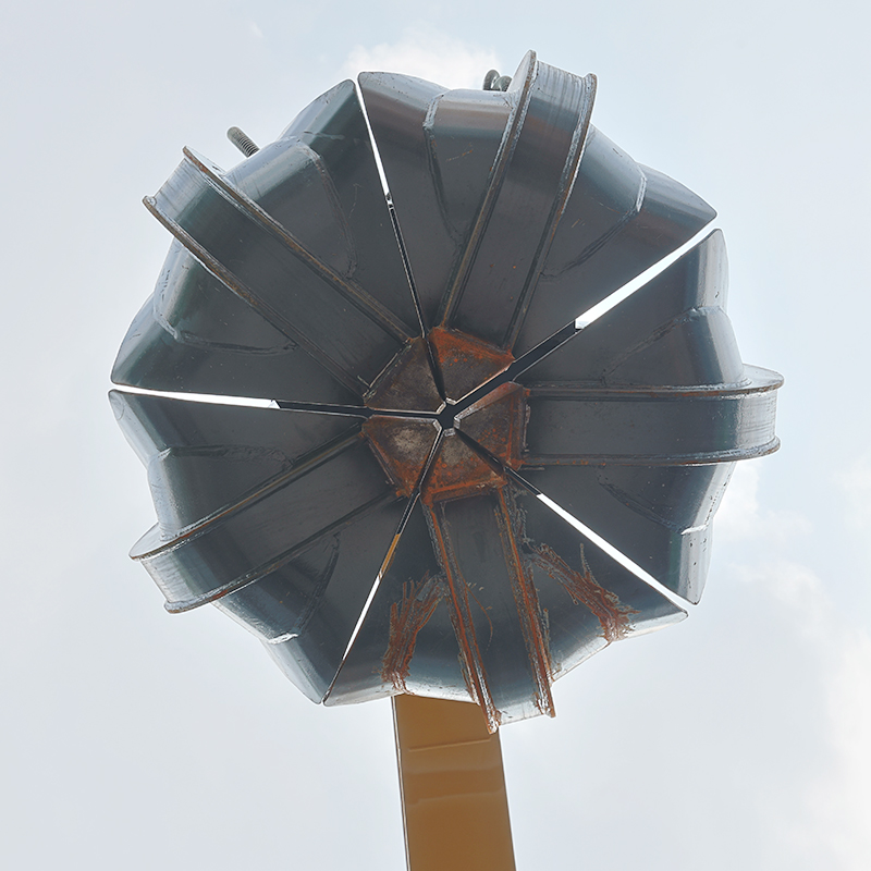
Structural Integrity, Steel Grades, and Design Geometry
Evaluating material composition prevents catastrophic equipment failure. Standard mild steel fails quickly under heavy torsional stress. It bends permanently when snagged on stubborn roots or concrete chunks. High-yield steel separates professional attachments from amateur tools. Materials like AR400 or Hardox offer immense tensile and yield strength. They absorb shock and spring back into shape. High-wear applications demand these advanced alloys to survive daily impacts without deforming.
Physical geometry dictates material retention efficiency. Tine spacing and overall jaw design must align with your specific job requirements. Different tasks require entirely different structural setups. Using the wrong jaw design guarantees dropped loads and wasted time.
| Grapple Type | Design Characteristics | Primary Applications |
| Root Grapples | Wide tine spacing, open bottom design. | Debris sifting, land clearing, brush removal. Let's dirt fall through. |
| Solid-Bottom | Closed bucket floor, independent top jaws. | Scrap metal, waste handling, loose gravel cleanup. |
| Bypass Grapples | Overlapping upper and lower tines. | Log handling, pipeline work, securing narrow diameter items tightly. |
Assessing vulnerability protection adds years to your equipment. You must evaluate the integration of cylinder guards and fully gusseted tines. Unprotected cylinders are prime targets for falling debris. A single dropped branch destroys a hydraulic rod instantly. Shielded hose routing mitigates common job-site damage. Hoses routed through the steel frame avoid pinching. Internal routing prevents branches from snagging and snapping your vital fluid lines.
Implementation Infrastructure: Valves, Plumbing, and Controls
Choosing the right control mechanism impacts daily operational efficiency. Operators usually choose between diverter valves and true third-function hydraulic kits. A diverter valve reroutes existing fluid flow. It creates sequential operation. You press a button to divert fluid from the loader curl function to the jaws. You cannot curl and bite at the same exact time. This slows down complex material sorting tasks.
True third-function hydraulic kits provide an independent circuit. They allow simultaneous operation. You can curl the bucket while simultaneously closing the jaws. This fluid multitasking increases cycle speeds dramatically. It gives operators precise, fluid control over unwieldy loads like loose brush or demolition scrap. For high-volume professional work, third-function valves remain the superior choice.
Exposed hydraulic lines pose severe plumbing risks. Hoses hanging loosely off the boom act like traps. They snag on debris, stretch, and eventually burst. We rely on strict best practices for hose sleeving and bulkhead fittings. Nylon abrasion sleeves protect rubber hoses from friction. Bulkhead fittings secure loose lines safely to the metal frame. Proper routing paths prevent pinching during maximum loader articulation.
Installation Realities to Verify
Measure quick-attach plate tolerances before attempting connection.
Verify all loader pin alignments using a digital caliper.
Confirm flat-face coupler sizing matches the carrier machine exactly.
Cycle the attachment without a load to check for pinched hoses.
Purge all trapped air from the newly connected hydraulic lines.
Operator Technique and Preventative Maintenance
The primary cause of premature structural failure is improper operator technique. Equipment limitations are real and must be respected. Using these attachments to bulldoze dirt destroys the structural frame. They are not built for prolonged ground-engaging push force. Prying stubborn tree stumps subjects the tines to extreme side-loading. Side-loading snaps hinge pins and warps the main torque tube. You must only apply force in the intended vertical clamping direction.
Identifying high-friction areas keeps your equipment running smoothly. Wear points need constant attention. Greasing pivot pins daily purges abrasive dirt from the bushings. You must inspect cylinder rods for vertical scoring. Scoring indicates internal contamination or bent rods. Checking the torque on structural bolts prevents catastrophic detachment during heavy lifts. Vibrations naturally loosen hardware over time. Regular torque audits save lives on the job site.
Operators must know how to spot warning signs early. Cylinder drift happens when jaws slowly open on their own. It indicates internal bypass leaks where fluid slips past worn piston seals. Structural micro-fractures often appear near heavily welded gussets. Catching a hairline crack early allows for a cheap weld repair. Ignoring it guarantees the entire arm will snap under tension later.
---
Conclusion
Optimizing equipment performance requires matching your attachment directly to your machine’s capabilities. Base your final purchasing decisions on the exact hydraulic output of your existing fleet, not on maximum listed capacities in a brochure. Understand the primary material density you process daily. This guides your choice between open-tine designs and solid-bottom models.
Audit your carrier machine’s GPM and PSI ratings today. Calculate your required usable payload by subtracting attachment weight from your loader limits. Finally, always request structural material certifications from the manufacturer to verify you are getting genuine high-yield steel before finalizing any procurement evaluation.
---
FAQ
Q: Why is my hydraulic grapple slowly opening on its own while holding a load?
A: This indicates cylinder drift caused by internal fluid bypassing. Worn piston seals allow pressurized fluid to slip past the internal barrier, causing a gradual loss of clamping force. It can also result from debris stuck inside a pilot-operated check valve. You will likely need to rebuild the cylinder with new seals or replace a faulty valve to restore holding power.
Q: Can I run a heavy duty hydraulic grapple on a compact tractor?
A: You can, but it is rarely advisable due to mathematical lift limits. A heavy attachment consumes the majority of a compact tractor's lifting capacity. This leaves little to no capacity for your actual payload. Exceeding these limits severely risks tipping the tractor forward or damaging the front axle under dynamic loads.
Q: What is the difference between a diverter valve and a third-function valve for grapple operation?
A: A diverter valve offers sequential operation; it steals fluid from the loader’s curl function, meaning you can only curl or bite one at a time. A third-function valve provides an independent hydraulic circuit. This allows simultaneous operation, letting you curl the loader arms and close the jaws at the exact same time for faster cycle speeds.
Q: How do I prevent hydraulic hoses from blowing on my grapple attachment?
A: Emphasize matching the attachment's maximum GPM rating to your machine's system flow. Pushing too much flow generates heat that melts internal seals. Avoid dead-heading the cylinders by holding the control button down after the jaws fully close. Ensure strict physical abrasion protection by using nylon hose sleeves and secure bulkhead routing to prevent snagging.
 English
 العربية
 Français
 Русский
 Español
 Português
 Deutsch
 italiano
 日本語
日本語 한국어
한국어 Nederlands
 Tiếng Việt
 ไทย
ไทย Polski
 Türkçe
 አማርኛ
አማርኛ ພາສາລາວ
 ភាសាខ្មែរ
 Bahasa Melayu
 ဗမာစာ
ဗမာစာ தமிழ்
தமிழ் Filipino
 Bahasa Indonesia
 magyar
 Română
 Čeština
 Монгол
 қазақ
қазақ Српски
 हिन्दी
 فارسی
فارسی Kiswahili
 Slovenčina
 Slovenščina
 Norsk
Norsk Svenska
 українська
 Ελληνικά
 Suomi
Suomi Հայերեն
 עברית
עברית Latine
 Dansk
Dansk اردو
اردو Shqip
Shqip বাংলা
বাংলা Hrvatski
 Afrikaans
 Gaeilge
 Eesti keel
 Māori
Māori


